Valve actuator
DC motor
Outline
There are two proven methods of operating an actuator even in the case of a power outage: The method in which a DC motor is used, and the method in which an air motor is used.
Historically, DC motor-type actuators have been used for emergency isolation valves in many power plants, as well as water supply and sewerage systems.
Matters to be noted as the requirements for DC motors
- 1. High starting torque characteristics appropriate for valve characteristics
- 2. Motors to which the line starting method is applicable
Because the motors to which the line starting method is applicable do not require current-limiting resistance at the time of starting nor a switching circuit, which are required for general-purpose DC motors, the circuit can be simplified.
Specifications of DC motor
- 1. Excitation type, self-excitation/cumulative compound type
- 2. Power supply
100 V, 110 V, 115 V
200 V, 230 V, 250 V (options)
3. Size (Output: Based on starting torque)
#2, #5, #7.5, #10, #15, #25, #40, #60, #80, #100, #150, #200
4. Hours of operation (Short-time rating)
20 % load (Intermediate load) #2 to #25: 15 mins #40 to #200: 5 mins
40 % load (Intermediate load) #2 to #25: 7.5 mins #40 to #200: 2 mins
5. Brake (Option)
DC motor connection diagram
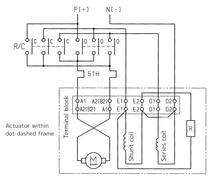
Explanation on symbols
R/C: Reversible electromagnetic switch
51H: Thermal relay heater
R: Discharge resistance
(Note 1) External wiring to E2 terminal is prohibited.
(Note 2) R represents discharge resistance.
(Note 3) When the motor size is #7.5 and larger (with interpole), B2 is used instead of A2 as the terminal marking.